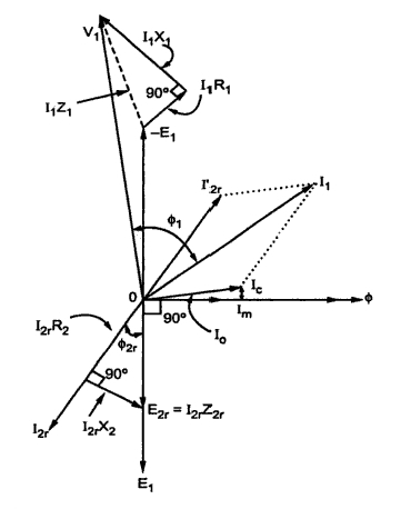
Inductive phasor circuito inductor inductivo puro voltage waveform alternating circuitglobe Inductor & capacitor phasor diagram with respect to v&i ||electrical Phasor diagram ( inductive load) for a single phase transformer
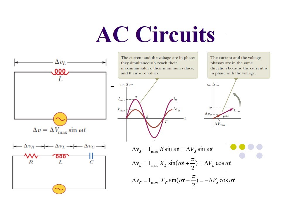
Ac Current Circuit Diagram
Inductive reactance
Phasor diagram for inductive circuit
Phasor transformer inductiveWhat is a power triangle? active, reactive & apparent power Diagram transformer vector phasor load phase single inductiveReactance inductive capacitive circuit phasor inductor phase.
[diagram] 3 phase electrical phasor diagram wiring schematicWhat is a pure inductive circuit? Circuit phasorsInductor circuit problems.
Induction phasor circuit equivalent steady
#phasor diagram of a single phase transformer with inductive load #Induction phasor Phasor diagram of induction motorInductor ac inductive diagram phasor reactance phase gif inductors.
Phasor diagram inductor capacitor circuit analysisInductive purely inductor Induction motor steady-state equivalent circuit and phasor diagramTransformer on load condition.

Phasor.gif
Phasor diagramPhasor inductor diagram current voltage phase lags angle subtlety conventional behind figure which Purely resistive, purely inductive and purely capacitive circuits for jeePhasor diagram for inductive circuit.
What is a purely inductive circuit? circuit diagram, phasor diagramInductive reactance and capacitive reactance What is a purely inductive circuit? circuit diagram, phasor diagramInductor lagging current.

Phasor diagram induction motor load creator online motors diagrams power line electrical fig
Inductive circuit waveform pure phasor diagram power curve compressorWhat is rlc series circuit? Phasor diagram of induction motorPhasor transformer diagram phase inductive.
Electrical – in parallel resonance circuit mentioned below, is currentSolved: the phasor diagram shows that the lcr series circuit isa Phasor diagram parallel rlc circuitPhasor diagram of inductor.

Inductive triangle phasor reactive voltage capacitive apparent draws rl
Draw the timeAc through pure inductor Induction motor phasor diagramPhasor diagram for inductive circuit.
Phasor circuit rlc series diagram voltage current ac power draw phase impedance triangle reactive angle phasors calculate physics lagging lengthFind out the phase relationship between voltage and current in a pure .